Nothing New Under the Sun
A Look at the CSM: Circular Sock Machine Part 1
Written by Sharon Nani
Previously Published in “Machine Knitters Source”
Article # Twenty
Issue: #100 (Jan/Feb 2001)
Do you want to get the men in your life more involved in your knitting interests? I did just that by restoring two late 1800 to early 1900 circular sock machines. During this exciting adventure, I learned that there was ‘nothing new under the sun’ as far as the comparison of the basic parts and mechanics of these machines and that of the ‘flat bed machines’ of today. This is indeed where some of our knitting machine roots came from. At the same time, both my husband and my dad learned an appreciation of how much goes into keeping all of our knitting machines working smoothly. I called upon them to de rust, weld, file burrs of obstructions, level, bend, oil, adjust and whatever they needed to do before I could successfully knit some beautiful circular socks. The beauty of these socks is that the ribbing is also knit circular. I have a great appreciation for their patience with me in all my requests to get things working perfectly – well perfectly for 100-year-old machines!
Compare the Parts and Mechanical Functions of the CSM’s (Circular sSock Machines) and the Flat Bed Machines
Major Division of Parts of Knitting Machines
I am not going to discuss the restoration process or history in this series of articles. There are some very good authorities and/or web sites that were very helpful to me in my adventure. I will list these at the end of the article for those of you that have your curiosity spurred. Also, make sure you see the CSM display and demo at MKS Forum 2001. My purpose for this article is to compare the parts and mechanical functions of the CSM’s (circular sock machines) and the flat bed machines that we traditionally knit upon today. I will follow in the next issues of MKS with this discussion and knitting techniques and fabrication on these old machines as compared with flat beds. And by the way, these machines knit more than just socks!
Let’s start with some facts. All knitting machines come in three basic categories of parts. These parts have the same mechanical functions, but the confusion comes when different brands of knitting machines refer to the parts by different names. Let’s eliminate some of the confusion by taking a closer look at the following three categories. (Flat Bed Terms)
- The Tension System
- The Needle Beds
- The Locks or Carriages
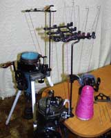
Special Note: I will use comparison tables and pictures to aid in the explanations. I have the manuals for three different CSM: The Auto Knitter- Buffalo, New York, USA (also manufactured under the name of Ainslie and Harmony) The Legare –Montreal, Canada [pictures are from these two machines which are mine: Figure 1: Legare with ribber is in the front on the table, the Ainslie is behind it on a stand], and the Gearhart –Clearfield, Pa USA. The sock knitter part name will be given first in bold type, the flat bed terminology in parenthesis and italics. Each will be in this order of knitting machine brand where applicable Ex. CSM: Auto Knitter, Legare, Gearhart, (flat bed: Passap, Brothers, Studio, Artisan).
The Tension System
The Tension System consists of the parts that guide or hold the yarn. Its purpose is to guide or direct the yarn from its source to the needles of the knitting machine. The source of yarn might be from a skein of yarn, hand spun yarn, or yarn already on a cone. It is very important that the yarn flow smoothly from its source through the tension system. Therefore, the first step 100 years ago, as it is today, is to rewind the yarn onto a bobbin (cone) with the use of a bobbin winder (yarn winder). Today, a lot of yarns can be purchased on cones thus eliminating this step.
 |
 |
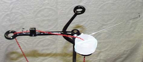 |
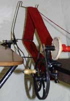
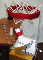
See Figure 2: It shows a bobbin winder, swift to hold the hand spun hank of yarn and wooden bobbins. A leather belt operates this winder as you turn the handle. See Figure 3: It shows a modern day yarn winder with a swift to hold the hand spun or hanks of yarn and its cones. After properly preparing the yarn, it is threaded through the Yarn Stand Top : Figure 4. (Yarn Tension Unit). It goes up through the eye of one of the short arms (yarn guides) through the lug (yarn guide) then under the Take-up Lock –needle latch -or check wire (tension disk) and down through the eye of the long arm (yarn guide). (Notice that I did rubber band a round of parifin wax on the short arm to help the cotton flow through the tension system smoother.)
Here is where the biggest difference is between the threading of the CSM and Flat Beds. The manual of all the CSM’s say to use the heel spring (take up spring) only when knitting the heel of a sock or toe, whereas the Flat Bed machines always use the take up spring. The function of the Tension disc with the take up spring is to hold the yarn in such a fashion that it creates tension on the yarn. As one of my men students who is a ‘fly fisherman’ observed, “Oh, you don’t want any slack in the line”. If there is slack yarn on Flat bed machines, loops will form on the edges of the knitting. This could also cause dropped stitches from the yarn not entering the hooks of the edge needles properly.
Since the CSM’s seem to have enough tension on the yarn by just going through the arms and take up lock, not to create these loops., I tried to determine why there is a difference at this point. The answer seems to be in the hint that the CSM’s do use the heel spring when they are knitting the heel and toe of the sock. The locks or carriages of the flat beds always knit by moving back and forth across the needle beds reversing directions at the end of each row, and the CSM’s also knit by cranking back and forth on the cylinder, reversing directions to knit the heel or toe, giving the yarn a chance to ‘slacken’, and thus the need for the heel spring. When the CSM is knitting circular and always cranking in the same direction (clockwise for my CSM’s) and with the position of the long arm of the yarn stand directly above the working area, a consistent and even yarn flow is obtained. Notice, that I used the word ‘consistent’. As a knitter on a CSM, if you did not crank in an even and consistent manner, this will cause an interruption in the yarn flow and could result in dropped stitches from the yarn not getting into the hooks of the latch needle correctly. This would be the same result as when the yarn flow is interrupted or too loose on the flat bed machines. I have found that with some yarns that do not flow as smoothly through the tension system on the CSM, using the heel spring on the tubular parts might be helpful.
The Needle Beds and Locks or Carriages
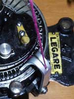
Once the yarn has gone through the Tension System, it has to have some means or device to get into the hooks of the latch needles. This device is a joining piece in between the other two categories of needle beds and locks / carriages. Some parts attach to the needle beds and some attach to the carriages. So I will discuss it now since it also deals with ‘carrying the yarn to the needles.’ First let’s look at the CSM. The yarn is threaded through the hole for the yarn on the Yarn Carrier. Figure 5 shows the yarn carrier on the Legare, which is an older machine. This yarn carrier only has a ‘height adjustment’. The height that the yarn carrier must be is such that the yarn must be feed into the hooks of the needles in the cylinder (front bed, passap, or main bed for holding position machines) at the exact time that the needle is in the upward position to receive the yarn. But at the same time, the yarn carrier must be high enough that it does not hit the top of the ribber dial needles (back bed, passap, or ribber bed for holding position machines) as these needles come outward from the ribber dial which sits on top of the cylinder.
This yarn carrier must also be close enough to the cylinder needles so that the yarn can get into the hooks . The hooks of the needles must be open to receive the yarn. Since there is not an adjustment for this close setting, you could only bend the yarn carrier forward or backward to fit. Since this setting would change with the different sizes of yarn, this was obviously an area, which needed improvement. See figure 5 left
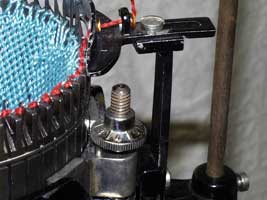
Now, look at figure 6, Left, which shows the yarn carrier for the Ainslie Auto Knitter. This yarn carrier has both a setting for the distance horizontally to the cylinder needles and the vertical height adjustment. So I assume that it is a newer CSM, about 1914 – 1917 or earlier
special note: the other cue to age was that it had a box of “Bundles for Britain” sock labels with it, which were for the socks made for the soldiers in WWI. See Figure 7
As you can see, these adjustments are critical to the knitting of the stitches. If just one of them is off, you will get dropped stitches because the yarn can not get into the hooks of the needles at the proper time. ( (2) Refer to the Supplement at the end of my Auto Knitter Instruction Manual at end of article) The settings for knitting tubular on the cylinder needles only are usually pretty easy.
It is when the ribber is joined, that the settings need compromising, especially since these antique machines have probably been whacked around a bit in the last 80 - 100 years or so. The Flat Bed machines have a similar part to the Yarn Carrier. The comparable part on the Passap machine to the yarn carrier would be the feeding eyelet which sits in the color changer until it is placed in the jaws of the back lock when it is time to knit and place the yarn into the hooks of the needles. The comparable part on the Japanese / Chinese machines which I call ‘the Holding Position Machines’, would be the yarn feeder slots in the Sinker Plates. I do not show pictures of the Flat bed machine parts as anyone reading this series of articles would probably have one of these machines.
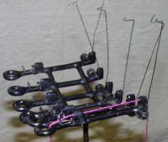
Speaking of color changers, check out Figure 8 to see that even CSM’s had color accessories. This is an accessory of a 6 color Yarn Stand Top for knitting argyle socks.
I am running out of space for this issue so I will continue the discussion of the needle bed and carriage categories in the next issues of MKS. For easy reference I include Table 1. This is a summary of the Comparative Part Names of Category 1: Tension System for CSM’s and Flat Bed Knitting Machines. Some of these items have not been discussed yet. Watch for the next issues of MKS for more information.
Comparative Part Names of Category 1: Tension System for CSM’s and Flat Bed Knitting Machines.
Table 1: Tension System Terminology (taken from Instruction or Parts Manuals from my machines)
| Circular Sock Machines: Auto Knitter (Ainslie) Legare 47 Gearhart |
Double Bed Machines Passap DM80 Passap E6000 |
Holding Position Machines Brother/Knit King Studio Artisan |
| Bobbin Winder, Swift, Bobbins | Yarn Winder, Swift, Cones | Yarn Winder, Swift, Cones |
| Yarn Stand Top, -- Yarn Guide | M Yarn Brake | Yarn Tension Unit |
| Short and Long Arms, lug | Yarn Guides | Yarn Guides |
| Take up Lock, needle latch, check wire | Tension Disc | Tension Disc |
| Heel Spring, Heel Spring, Take up Spring | VM Tension Arm | Take up Spring |
| Yarn Carrier, Yarn Carrier, Carrier Bar | Feeding Eyelets, color changer and Jaws of the Back Lock | Yarn Feeders A and B in the Sinker Plates (some have plating slots) |
| 6 color Argyle Yarn Stand Top | 4 color changer | 4 color changer |
| Buckle and Heel Weights – Buckle Brace and Weights | Cast on Combs and Weights | Cast on Combs and Weights |
| “Set Up”, “Set Up Basket”, “Set Up” | Cast on Combs and Weights | Cast on Combs and Weights |
| Heel Hook, Heel Hook, Hold Down and Heel Hook | Heel Grip | Claw Weight |
| Yarn Carrier – Yarn Carrier – Carrier Bar | Black, Blue, and Orange Strippers | Sinker Plates |
RESOURCES FOR CMS
1 Smola, Bonnie. Sock Machine Knitting News Letter. 304 Scott Hollow Rd, Monona, Iowa 52159. email: smolas@netins.
CSM knitters are extremely helpful on the sock-machine list: (no charge) Subscribe to the sock-machine knit list by sending email to “Socks-Subscribe@topica.com.AUTHOR NOTE 3-24-2008: Since this article was written several years ago: newsletter contact and sock machine knit list may be outdated, please do a search for new information.
There is a wonderful picture museum and maintenance tips by Ralph Kanko, “The Cranky Knitter”
2 The Auto Knitter Hosiery Co., Inc. The Auto Knitter Instruction Book Eighteenth Edition. Buffalo, N. Y., 1922.
“For the proper position of the yarn carrier see that the hook of the cylinder needle in action just reaches the top of the hole in the yarn carrier head and that the yarn carrier is as close as possible to the needles without touching them. Then adjust the height of the dial by means of the Height Regulating Screw (J-1) until the dial needles (with latches open just pass under the yarn carrier, but do not rub or touch against it."
Visit us on facebook too ~ page is in development
